 I.
The Control System I.
The Control System

Figure 1 - The Control System
The automatic control system process.
 II.
Sensors II.
Sensors
Thermistor
A non-linear device whose resistance varies with
temperature. Thermistors are used at temperatures under 500°F. Fragility
limits their use in industrial applications.
Resistance Temperature Detector (RTD)
Changes in temperature vary the resistance of an element,
normally a thin platinum wire. Platinum RTDs find application where high
accuracy and low drift are required. 3-wire sensors are used where the
distance between the process and the controller is more than several feet.
The third wire is used for leadwire resistance compensation.
Thermocouple
A junction of two dissimilar metals produces a millivolt
signal whose amplitude is dependent on (a) the junction metals; (b) the
temperature under measurement. Thermocouples require cold-end compensation
whereas connections between thermocouple wire and copper at the controller's
terminal block produce voltages that are not related to the process
temperature. Thermocouple voltage outputs are non-linear with respect to the
range of temperatures being measured and, therefore, require linearization
for accuracy. Thermocouple junctions are usually made by welding the
dissimilar metals together to form a bead. Different thermocouple types are
used for various temperature measurements as shown in Table 1.
Thermocouples are the most commonly used industrial sensor because of low
cost and durability.
Thermocouple
Type |
Wire
Color |
Useful
Temperature
Range °F |
J
K
T
R/S |
White
Yellow
Blue
Black |
32 to 1300
-328 to 2200
-328 to 650
-32 to 2642 |
Table 1
Other
Other temperature sensors include non-contact infrared
pyrometers and thermopiles. These are used where the process is in motion or
cannot be accessed with a fixed sensor.
 III.
Sensor Placement III.
Sensor Placement
Reduction of transfer lag is essential for accurate
temperature control using simple temperature controllers. The sensor, heater
and work load should be grouped as closely as possible. Sensors placed
downstream in pipes, thermowells or loose-fitting platen holes will not
yield optimum control. Gas and air flow processes must be sensed with an
open element probe to minimize lag. Remember that the controller can only
respond to the information it receives from its sensor.
 IV.
Process Load Characteristics IV.
Process Load Characteristics
Thermal lag is the product of thermal resistance and thermal
capacity. A single lag process has one resistance and one capacity. Thermal
resistance is present at the heater/water interface. Capacity is the storage
capacity of the water being heated. Sometimes the sensor location is distant
from the heated process and this introduces dead time. (See Figure 2a)
Introduction of additional capacities and thermal resistance changes the
process to multi-lag. (See Figure 2b and 2c)

Figure 2 - Various Processes
 V.
Control Modes V.
Control Modes
On-Off
On-Off control has two states, fully off and fully on. To
prevent rapid cycling, some hysteresis is added to the switching function.
In operation, the controller output is on from start-up until temperature
set value is achieved. After overshoot, the temperature then falls to the
hysteresis limit and power is reapplied.
On-Off control can be used where:
 The process is
underpowered and the heater has very little storage capacity. The process is
underpowered and the heater has very little storage capacity.
 Where some temperature
oscillation is permissible. Where some temperature
oscillation is permissible.
 On electromechanical
systems (compressors) where cycling must be minimized. On electromechanical
systems (compressors) where cycling must be minimized.

Figure 3 - On/Off Control
Proportional
Proportional controllers modulate power to the process by
adjusting their output power within a proportional band. The proportional
band is expressed as a percentage of the instrument span and is centered
over the setpoint. At the lower proportional band edge and below, power
output is 100%. As the temperature rises through the band, power is
proportionately reduced so that at the upper band edge and above, power
output is 0%

Figure 4 - Proportional Control
Proportional controllers can have two adjustments:
Manual Reset
Allows positioning the band with respect to the setpoint so
that more or less power is applied at setpoint to eliminate the offset error
inherent in proportional control.

Figure 5 - Manual Reset
Bandwidth (Gain)
Permits changing the modulating bandwidth to accommodate
various process characteristics. High-gain, fast processes require a wide
band for good control without oscillation. Low-gain, slow-moving processes
can be managed well with narrow band to on-off control.

Figure 6 - Proportional Bandwith
The relationship between gain and bandwidth is expressed inversely:

Proportional-only controllers may be used where the
process
load is fairly constant and the setpoint is not frequently changed.
Proportional with Integral (PI), Automatic Reset
Integral action moves the proportional band to increase or
decrease power in response to temperature deviation from setpoint. The
integrator slowly changes power output until zero deviation is achieved.
Integral action cannot be faster than process response time or oscillation
will occur.

Figure 7
Proportional with Derivative (PD), Rate Action
Derivative moves the proportional band to provide more or
less output power in response to rapidly changing temperature. Its effect is
to add lead during temperature change. It also reduces overshoot on
start-up.
Proportional Integral Derivative (PID)
This type of control is useful on difficult processes. Its
integral action eliminates offset error, while derivative action rapidly
changes output in response to load changes.
 VI.
Proportional Outputs VI.
Proportional Outputs
Load power can be switched by four different proportioning
means:
Current Proportional
A 4-20 mA signal is generated in response to the heating %
requirement. This signal is used to drive SCR power controllers and
motor-operated valve positioners.
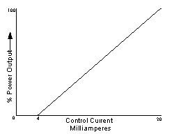
Figure 8 - Control Current vs. Power Output
Phase Angle
This method of modulating permits applying a portion of an
ac sine wave to the load. The effect is similar to light dimmer function.
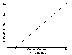
Figure 9 - Phase Angle
Time Proportioning
A clock produces pulses with a variable duty cycle. Outputs
are either direct- or reverse-acting. Direct-acting is used for cooling;
reverse-acting for heating.
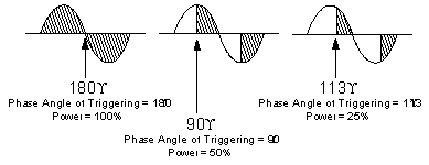
Figure 10 - Time Proportioning
Cycle Time
In time proportioning control the cycle time is normally
adjustable to accommodate various load sizes. A low mass radiant or air
heater requires a very fast cycle time to prevent temperature cycling.
Larger heaters and heater load combinations can operate satisfactorily with
longer cycle times. Use the longest cycle time consistent with ripple-free
control.
 VII.
Power Handlers VII.
Power Handlers
Power is switched to an electric heating load through the
final control element. Small, single-phase 120/240 V loads may be connected
directly to the temperature controller. Larger, higher voltage heaters must
be switched through an external power handler. Power handlers are either
large relays (contactors), solid-state contactors or power controllers.
Mechanical Contactors
They are probably the most widely used power handlers. They:
Are rugged.
Have fuses to protect against burnout due to shorts.
Will wear out in time due to contact arcing.
Cannot be fast-cycled for low-mass loads.
Produce RF switching noise.
Solid-State Contactors
They are often used on loads requiring fast switching times.
They need heat sinking and I2T fuse protection. SCR power controllers. These
devices switch ac power by means of thyristors (SCRs). These are solid-state
devices that are turned on by gate pulses. They have unlimited life and
require no maintenance. SCR controllers are available for switching single-
or three-phase loads in zero crossing/burst firing (Figure 12) or
phase-angle modes (Figure 10).
SCR power control selection by switching method can be simplified, as
follows:Use zero crossing for all standard heater applications.
Specify phase angle:
When soft start (ramp voltage to peak) is required on high inrush heater
loads.
If voltage limit is needed to clamp the maximum output voltage to a level
lower than the supply voltage.
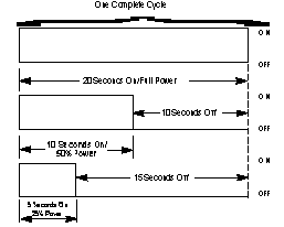
Figure 11
 VIII.
Heater and Power Control Connections VIII.
Heater and Power Control Connections
Power controls are connected to the control signal and load.
(Figure 12) The control signal to the power controller may originate
from a manual potentiometer, PLC or temperature controller. This signal is
normally 4-20 mA, but can be other currents or voltages. An increase in the
signal level produces a corresponding increase in power controller output.
Calculation of SCR size for various voltages and heater sizes is as follows:
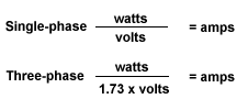
Equations to Calculate Power and Current
watts = total heater watts
volts = line voltage
amps = total line current
SCRs should not be sized at exactly the heater current requirement because
heaters have resistance tolerances as do line supplies.
Example:
A single-phase 240 volt heater is rated at 7.2 kW
7,200 ÷ 4240 = 30 A
If the heater is 10% low on resistance, at 240 V, the heater will draw 33
amperes. Damage to fuses will result. Power controllers must be properly
cooled and, therefore, the mounting location should be in a cool area. SCRs
dissipate approximately 2 watts per ampere per phase.
Proper fusing is essential to protect the SCR devices from damage due to
load short circuits. The type of fuse is marked I2T or semiconductor.
Only SCRs designed to drive transformers should be used for that purpose.
SCR power controllers must never be used as disconnects in high-limit
applications.
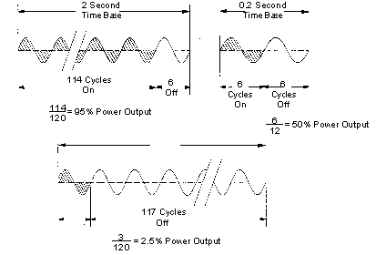
Figure 12 |
![]()